CEA - HP Scientific Calculator Acquisition System
Eng. Aer. Frederico Mol Alvares da Silva
Eng. Aer. Paulo Henriques Iscold Andrade de Oliveira
Description
This system is based on a PIC Microcontroller to provide analog to digital conversion and serial communication. Using PIC chip technology, the system offers low cost, adaptability, reliability, and compact Data Logger function. The system was designed to process up to eight analog channels (0 to 5V) with 10bits data precision, enough for most applications. After A/D conversion, data is sent through serial port (RS232) to a portable HP48G scientific calculator or Palmtop. The data is formatted inside the calculator, and finally, available to read. Adjustments such offset and channel scale can be made before the acquisition through HP48G software. After acquisition and data processing, performed by HP48 or Palmtop, the data can be send to a PC for best data visualization and post-processing. The advantages of this system are low cost design, flexibility, reduced size and weight.
Aplications
Engineering Labor Teaching
Racing Car Data Logger
Light Aircraft Data Logger
Data Measurement
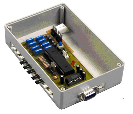
Materials
Microchip PIC16F877 Microcontroller
MAX232 serial driver
HP48G personal calculator or Palmtop
Knowledge
PIC assembler programming
HP48 RPL language programming
Palmtop C++ programming
Functional Diagram
The data logger circuit requires a DC regulated power supply, or a battery for mobile applications. Eight analog (0 to 5V) sensor inputs can be plugged simultaneously, and the PIC based circuit converts the analog inputs to digital. The A/D conversion is made with 10 bit data precision.
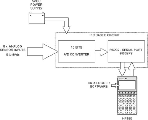
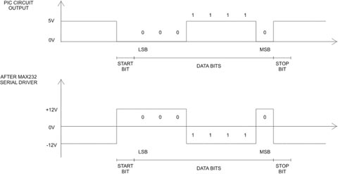
After all A/D conversion of each input (channel) is done, the data is sent to HP48G through serial port RS232 at 9600bps, eight data bits, no parity, one stop and start bit (8N1). The serial interface between PIC and HP48 is made with MAX232 serial driver. This IC changes the 0 to 5Vdc voltage level from PIC circuit to +12V -12V RS232 standard.
To activate PIC circuit data sent, one byte needs to be sent from HP48, see HP48 RPL code.
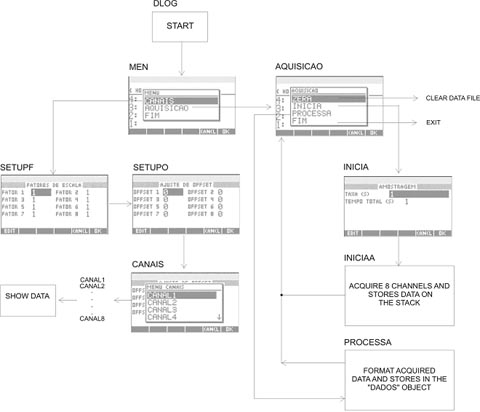
The HP48 software fluxogram is shown below. The variable names are shown in the top of the boxes on fig. 3. To start the software just run the DLOG variable, the first screen appears and the software can be used. To view data before acquisition, for data calibration, choose the option “CANAIS”, and input the scale factors and offset values of each channel. The default are “1” for scale factors and “0” for offset values. Choose the channel that you want to calibrate or view. Only one channel can be viewed at once.